- Laser cutting is a process where material is placed in the X-Y plane and a
LASER (Light Amplification by Stimulated Emission of Radiation) is moved across the profile to be cut out.
- A laser can be focused to a tight spot, which allows the beam to “cut” at the position.
- The high intensity of the beam causes the material to be vaporised (cut away).
- Since the light can be focused, a very thin cut is made. Electronics and machine control make the cut precise and repeatable.
- The laser can be programmed to have a continous wave or pulsed repeatedly to produce the cut.
- The process of laser cutting is controlled by:
-> The speed of the movement of the laser
-> Slow speeds allow the laser more time over the material and cuts deeper and more intensely.
-> Slow speeds also cause charring of the material.
- The intensity of the laser:
-> Higher intensities of the laser can cut deeper
-> Higher intensities are sometimes required as the material is more dense than others
- The number of pulses per second.
-> Most lasers are pulsed. The higher the number of pulses per second give higher intensities and prolonged exposure to the laser.
-> Higher pulsing reates are required for dense material
- Most lasers settings come with recommendations from the manufacturer or the Technicians and are dependent upon:
-> The material (e.g. wood, acrylic, paper)
-> The thickness of the material
-> The color/coloration of the material.
Fusion 360 preparation for Laser Cut
- When designing in Fusion 360, we have the ability:
-> of modelling an object in 3 dimensions
-> to check for joints and obstructions
-> to check the aesthetics of the model.
- However, when we decide to laser cut the object we need to obtain the profile of the object and export it in a format that the cutting software recognises.
- This applies to other design software as well e.g. Illustrator, Rhino
- The preferred file formats required for laser cutting are:
->
AutoCAD DXF (Data eXchange Format)
->
PDF (Portable Document Format)
->
SVG (Scalable Vector Graphics)
- For our laser cutters, the software used to check and finalise your cuts is the
CorelDraw Graphics Suite which is able to handle both Vector and Raster images suitable for cutting and engraving. This is traditionally the recommended software though it is fast being replaced by Inkscape, RDWorks (for China Lasers) because of its costs.
- The workflow is as follows:
-> Obtain the 2D profile of the object face
-> Export the profile as DXF
-> Import the DXF file into CorelDraw
-> Make necessary changes and adjustments
-> Send/print the profile to the lasercutter
- This workflow applies to all Lasercutters.
Obtaining DXF profiles from Fusion 360
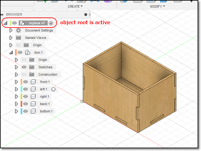
For this example, we will use the box profile in which I need to extract the side, front and base of the box. We assume that the box has been designed as in the Parametric Box.
- Open your design in Fusion 360.
- In the Object Browser, expand and show the bodies/component list.
- If you have multiple components, make sure that the root or top-most object is selected.
- Open your design in Fusion 360.
- In the Object Browser, expand and show the bodies/component list.
- If you have multiple components, make sure that the root or top-mose object is selected
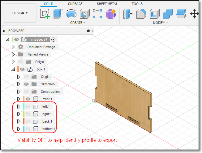
- Select the body which you want to extract the profile.
- To help you, you can turn off the bodies which are not of interest
- In this case only the FRONT component is selected
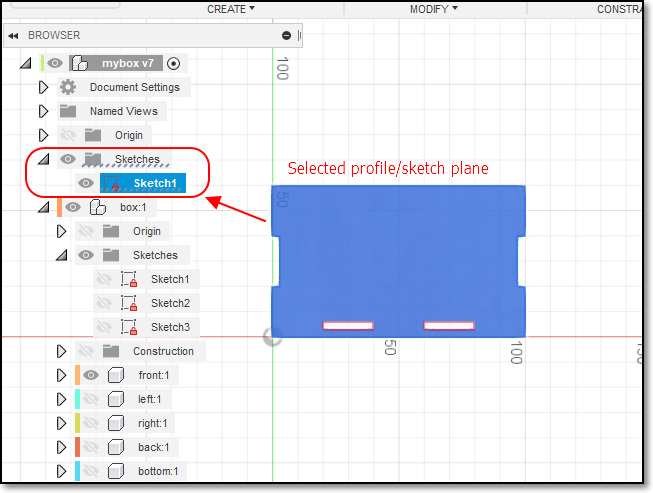
Click onto the body surface to select the sketch plane.
- Make a new sketch on this FRONT plane:
1. Create > Create Sketch
2. Select(L-Click) the body surface to select the sketch plane.
3. Important Click again on the profile (it should turn BLUE), showing you the sketch profile.
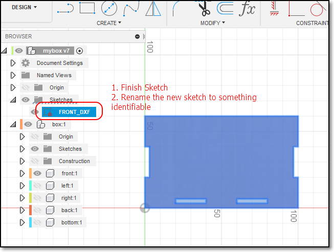
4. Click FINISH SKETCH
5. Your sketch should be located in the Object Browser > Sketches
6. Select “Finish Sketch”
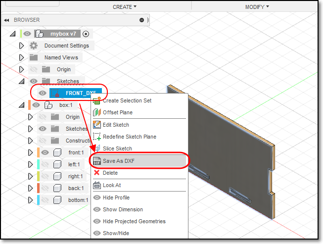
7. Rename the sketch to identify it (e.g. FRONT_DXF)
- Export the profile as DXF:
1. Right-click on the Sketch FRONT_DXF
2. Select the Save As DXF Option
3. Enter an appropriate name for the file e.g. FRONT
4. enote of the Folder where the document is to be saved.
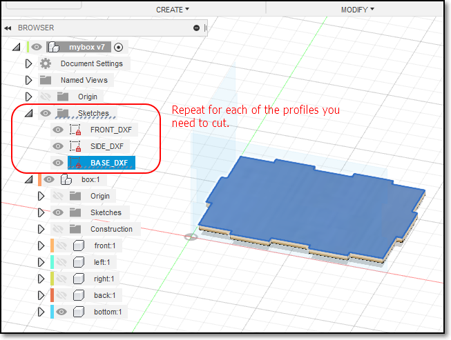
- Repeat the above steps for each of the profiles that you want to cut FRONT, SIDE, BASE
- The Front and Sides are mirrored, and are similar, so only one profile need to be saved.
Kerf
- Laser cutting is very precise, giving you accuracies and repeatability in terms of tenth’s of a millimeter.
- However, sometimes you would like to create Press-Fit objects that are assembled without glue or any other materials.
- When a laser cuts through material, some material is removed in the process. The material that is removed is called the Kerf.
-> The kerf in laser cutters is very small (approx. 0.3 ~ 0.8 mm) depending on the material and how it is cut.
-> If we can calculate the Kerf (through experimentation) we can make adjustments to ensure that the cuts are press-fit.
- Adjusments are usually made by:
-> decreasing the size of the “holes”
-> increasing the size of the “tabs”
- Can be done parametrically by adding an adjustment value to compensate for the kerf.